Tech Notes: Testing Wires and Cables
 January 22, 2018
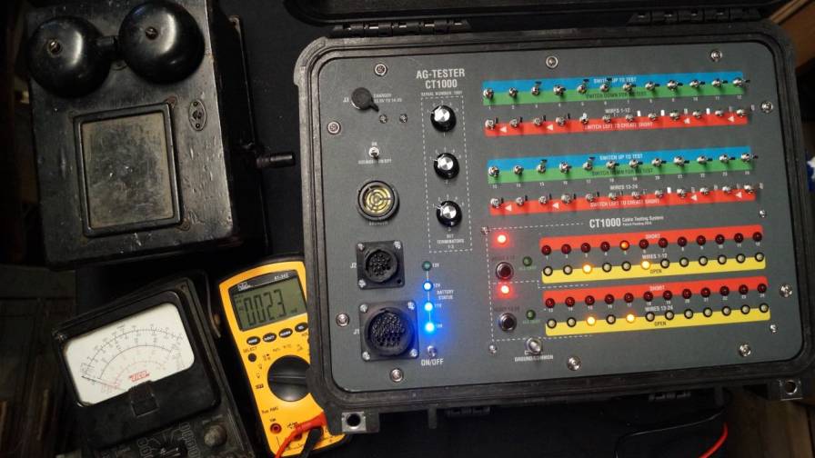
The CT1000 Cable Testing System was developed by Ag-Tester to allow a single user to fully test and isolate trouble with complex cables associated with field vehicles and implements without removing the cable harness from the machine.
Cables can be easy to troubleshoot, if you observe the correct process, have a meter of some sort and two people. This issue of Tech Notes will lay out the processes involved and hopefully give you a new skill set as you troubleshoot field electronic systems.
The diagnostic process can be time consuming but will identify any potential trouble.
The process has stayed the same from the very early days of telephone systems back in the early 1900s, here in the U.S. Unfortunately, the tools haven’t changed much either. They look different and some are more complicated, but they all will check a cable properly.
In the early 1900s a simple “ringer” did the trick. Turn the crank, and if the bell sounded there was a connection.
Analog meters were developed with digital meters coming along in the 1970s.
The CT1000 Cable Testing System was developed by Ag-Tester to allow a single user to fully test and isolate trouble with complex cables associated with field vehicles and implements without removing the cable harness from the machine.
Testing Cables Using an Ohm Meter
Testing cables when the technician only has access to one end of the cable for a meter connection can be done with a traditional ohm meter or continuity tester. Completely testing a harness can be very time consuming and it’s very easy to miss intermittent connections.
 Figures 1 and 2. Click to enlarge. |
 Figure 3. Click to enlarge. |
 Figure 4. Click to enlarge. |
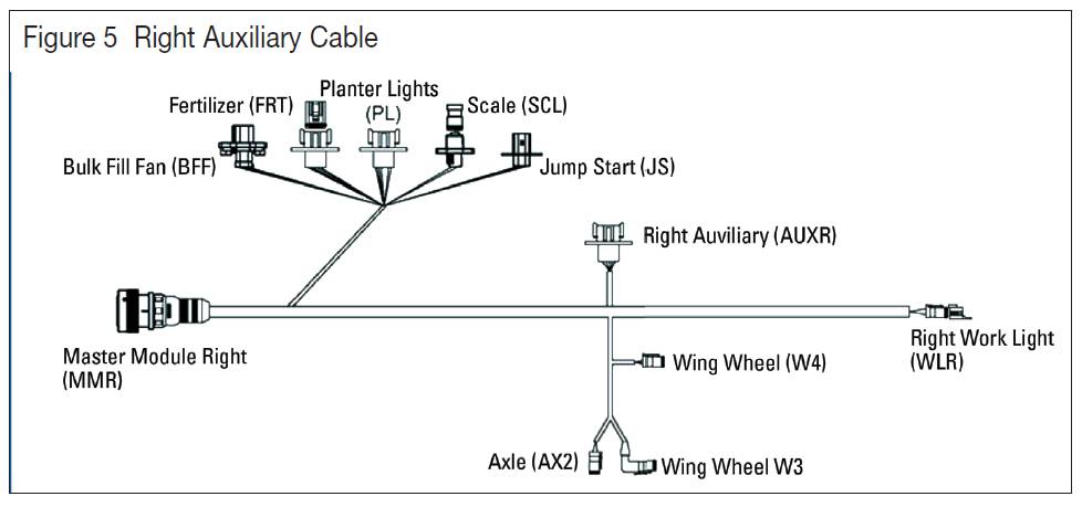 Figure 5. Click to enlarge. |
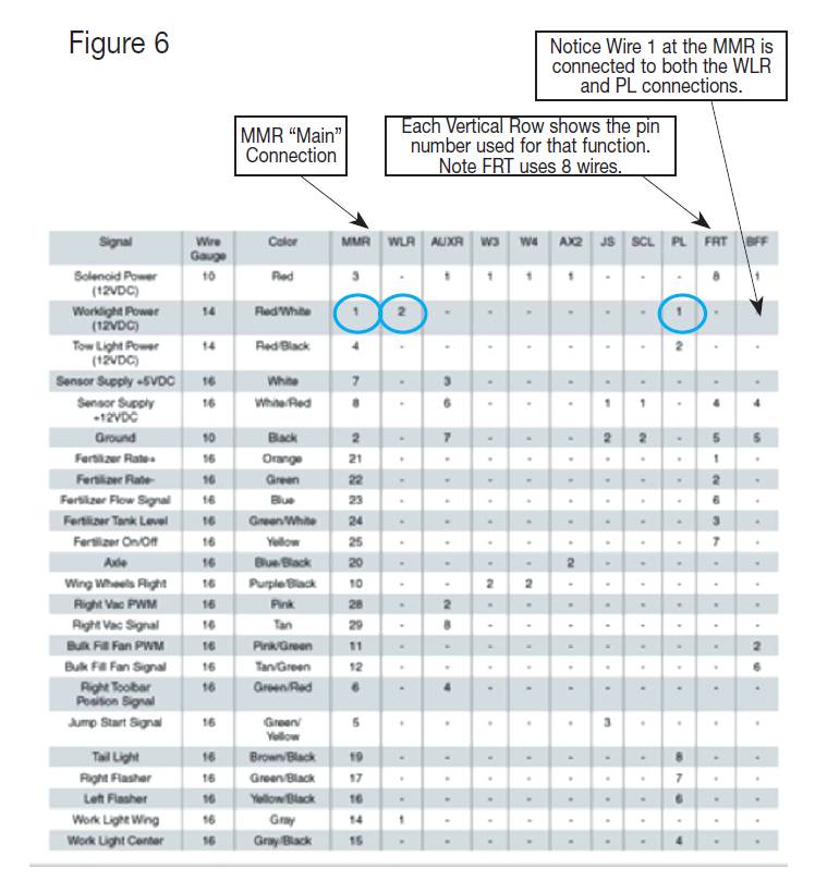 Figure 6. Click to enlarge. |
The process used for testing is the same today as it was many years ago. Two people are generally required. One tech is at the cable end with a meter while the other tech moving a jumper wire at the opposite end of the harness.
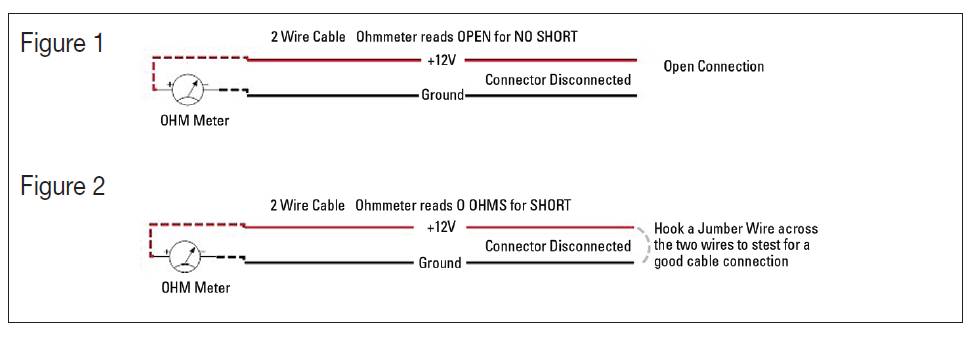
Basic examples using an ohm meter are shown in figures 1 and 2.
These two simple steps will confirm the wires are not shorted together and the wires are not broken.
Multi-wire cables can be tested using the same process as shown in figures 3 and 4.
Test the wires one at a time for continuity, “zero ohms.” Then check for shorts between each wire. Establish a COMMON connection point for the test. We’re using the BLACK wire #1 as common.
When checking for shorts between wires check the wires one at a time. Use one wire as the COMMON. We’re using the BLACK wire #1 as common.
To check wire 5 for shorts hook the meter leads to 1 and 5. Then hook connect jumpers from wires 1 to 2, 1 to 3, and 1 to 4. That shorts all wire to common except the wire 5 being tested. Then move the meter leads to 1 and 4 while shorting to common wires 5, 3, and 2 to the common #1 wire.
Repeat the process until all the wires have been checked. The process is time consuming, but it works.
Where things really can get complicated is when multiple connectors are involved and there are multiple wires connected to a single wire connection, like the one shown in figure 5. Many times the power wires, signal lines and others are common to multiple connectors.
This cable has 24 wire connections at the MMR connector. The MMR is then hooked to 10 different connectors going to different pieces of the system.
The wiring table in figure 6 shows how the connections are made from the MMR connector, out to the system components. You will need to have this chart information to do any troubleshooting on equipment cables. This should be available from the system manufacturer.
Even this complex cable can be tested with the old ringer or any meter but it is very time consuming and there are lots of places for errors to occur.
If you plan to do continuity checks as we addressed earlier, the process stays the same but you’ve got to unplug all the other components that share the wire connection, then check each cable drop separately.
Using Terminators
I found it to be very useful to build terminators to aid in my ability to quickly check cables that we use a lot in the field. Connecting a resistor across the wires being tested gives a reference point that can be read on you ohm meter. I use 600 ohm resistors.
The resistance reference gives an ohm meter reading that is easily predictably as resistors are connected in parallel. Where multiple connectors having wires in common an entire cable harness can be checked completely in one test.
When resistors are hooked in parallel, the resulting reference is equal to the resistor value divided by the number of resistors. Two 600 ohm resistors hooked in parallel creates a 300 ohm result. Three hooked in parallel equals 200, 4 would be 150 ohms and so on.
We build terminators for all types of cables for the CT1000 Harness Tester. If you do a lot of RAVEN maintenance, build RAVEN terminators. Having that 600 ohm reference really helps when in the field. I allow for 10% error and then come to a conclusion any reading below 540 ohms indicates a partial short and anything over 660 ohms indicates an open connection. If two terminating resistors are installed I come to the same conclusion with 300 ohms as the starting point.
Once you’ve built up your terminators they will be available when you’re in the field troubleshooting. They allow a single technician to go through the troubleshooting process without the helper moving around jumpers.
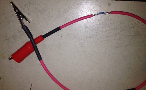
You can make a test terminator using alligator clips, with the resistor installed in-line between the clips.
You can make a test terminator using alligator clips, with the resistor installed in-line between the clips. Shrink tubing protects the resistor connection.
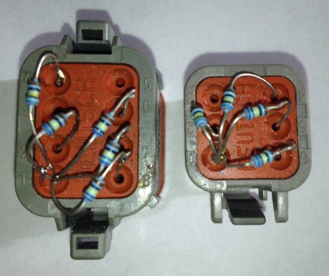
If you are going to build terminators to plug in the cable drop point like those shown in this photo, be careful in the connector selection process.
If you are going to build terminators to plug in the cable drop point like those shown in the photo below, be careful in the connector selection process. You can see in the placement of the resistor leads shown which connection was selected as common for the test process.
It takes some time to develop the terminators but countless hours will be saved doing diagnostics in the field.
The basic process of troubleshooting cable harness remains the same as it was 100 years ago. You will be successful if you follow the exact processes I’ve shown.
I built my CT1000 cable harness tester for a large agricultural company. Their goal was to provide their dealers an efficient method of testing cable harnesses. The CT1000 uses the exact same process as shown with a lot of visual aids and alarms. Terminators are installed and the Tester is looking for the constant resistance, activating alarms if that condition is in error.
I hope this addition of Tech Notes has added to your skill set. I look forward to your comments and questions. Feel free to contact me with any questions and comments at [email protected]. Please take a look at my Website agtester.com for field troubleshooting tools including the CT1000 cable harness tester.
Remember Tech Notes is for the field guys. Please pass it on.
Subscribe Today For
