Tech Notes: Building TEE Harnesses
 March 7, 2018
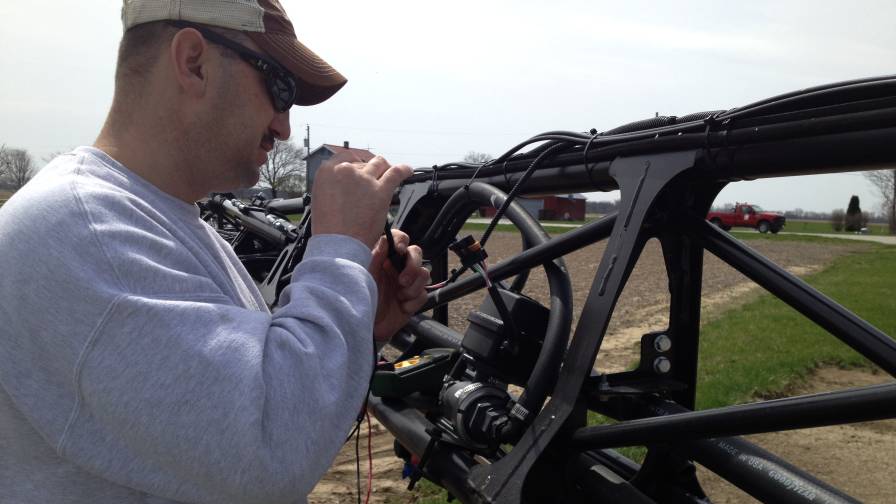
TEE Harnesses are a big component to the hand-held testers John Dignan created at Ag-Tester.
I can’t tell you how many times over the years I’ve needed to know the voltages or signals present on wires feeding valves and sensors when in the field doing troubleshooting. Anything from broken wires to corroded connectors to display programming errors can cause the result, “It’s Not Working.”
Eventually, many times as a last result, I just cut into the wires to allow my meter to be connected. Doing that does allow for a good meter connection but creates an additional problem, “now you have bare wires where a good cable may have already existed.”
The other testing method used by most field techs is to disconnect the component and plug the meter into the connections coming from the display. The flaw in doing this type of test is many cable and connection errors will only show up when connected and operating. I recall many times that flow meters wouldn’t work yet when you’d check the voltages coming from the display, everything looked good. The assumption at that point is “the flow meter must be bad” — replace it.
A few hundred dollars and a couple days later you find the new meter doesn’t work either. Many times the cause is corrosion on one of the connections or somewhere in the wiring.
Corrosion in an electrical circuit only shows its ugly head when current flow through the circuit. Test meters are designed to NOT cause current flow. You can’t see the corrosion problem until the circuit is complete and current is flowing. This is worth understanding. Review Tech Notes covering Ohms Law.
The law states that (voltage drop = amps X ohms). If there is no current flow, zero amps, there is no voltage drop. On the other hand a small current, .050 amps with a 100 ohm resistance from corrosion will cause a 5-volt drop. The only way to detect that is with the component connected.
Using TEE Harnesses
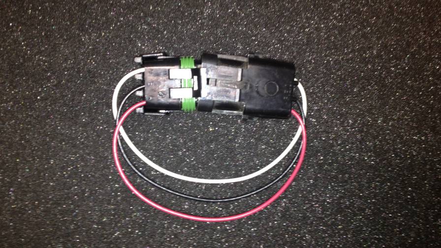 Set of Male and Female connectors. |
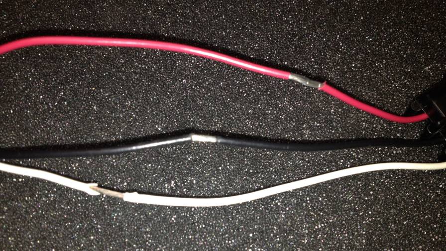 Stagger the cuts. |
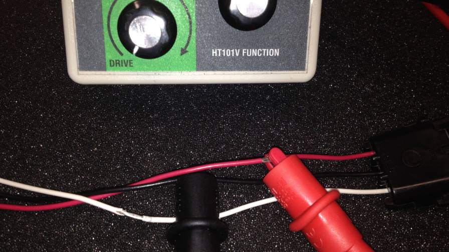 Adapter allow you to tie into the component. |
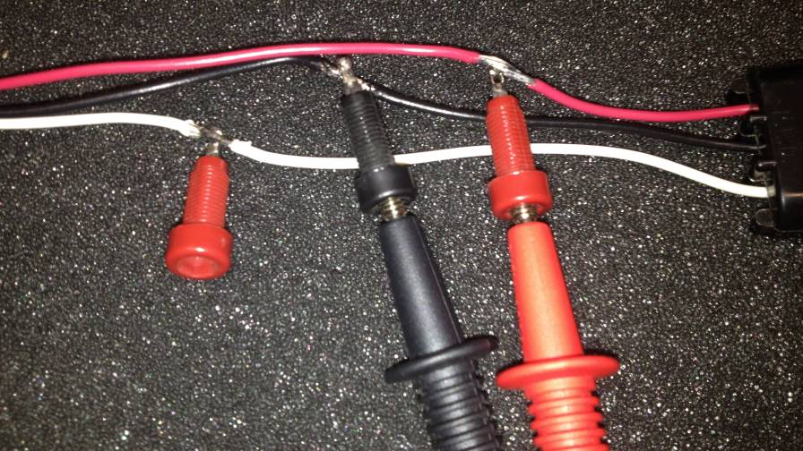 Tip jacks enable a solid connection. |
 How the Ag-Tester Sensor Tester is wired. Click to enlarge. |
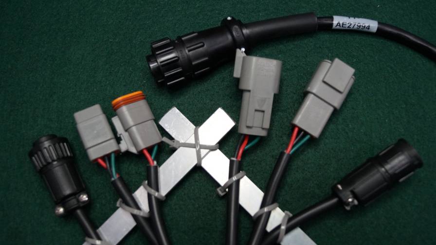 In-line sensor cable interfaces with Raven components. |
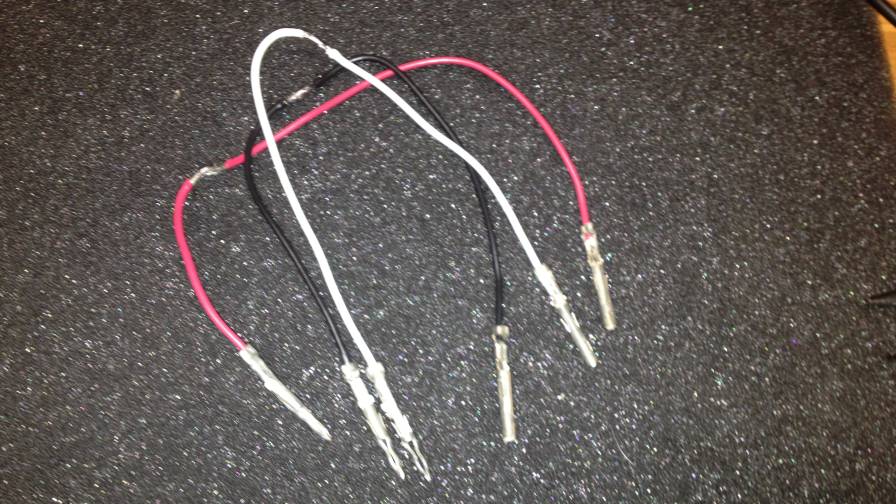 Connector pins. |
TEE harnesses are a big component to the hand-held testers I created at Ag-Tester. You can build your own using lots of different methods.
The basic TEE cable can simply be a set of male and female connectors that match the component you want to tie into with wires between the connectors to allow your meter to be tied in. Be very careful identifying the pin numbers.
Cut into the wires, staggering the cuts. This helps eliminate shot circuits when testing.
With a simple adapter, you can now tie into the component with the system in full operation so you can really see what’s happening in the circuit.
You could add tip jacks to clean up your adapter and fully insulate the connections. Tip jacks allow the meter tip to be plugged in for a solid connection. They are available at electronic supply houses.
I use tip jacks on my hand-held testers to allow for that connection. The back of the sensor tester has a seven pin connection that allows for different adapter cables to be easily hooked up. You can build the same type of connecting box yourself and use the existing meters and test tools you have on hand.
Please notice in the diagram we are separating the connection of the signal wire between the display and the sensor. Then for a true in-line connection the signal wire is reconnected in the tester. You’ll notice the “digital and analog simulator” connection. Sending the signal to the display ensures the connection from the TEE connector to the display is good.
The 5- and 12-volt connections allow the tester to feed power directly to the sensor to allow a test independent of the display. A different cable is used for this “stand-alone” test process.
This in-line sensor cable is designed to interface with Raven sensor components. There are two sets of three connector types available. The connections at the left side of the photo feed the sensor while the right side feeds the display.
All three connections are hooked in parallel and terminate at the seven pin amp connection which plugs into the tester.
It’s a very reliable way to tie into components while they are on the machine.
There are lots of possible connector types and wiring configurations you’re going to run into. Many times when on the job you don’t have the right connectors with you but need to get the machine back in the field.
If you’ve got connector pins with you on the job you can quickly build a test TEE cable by simply installing the pins on wires and plug the pins in without the connector body. Here you’ve got to be real careful but it may save you a lot of time.
I hope this addition of Tech Notes has been helpful. I look forward to your comments and questions along with column suggestions. Feel free to contact me with your comments at [email protected]. Please take a look at my Website, agtester.com, for field troubleshooting tools including the HT101V Valve Tester and the HT101S for sensors.
Remember Tech Notes is for the field guys. Please pass it on.
Subscribe Today For
